Try searching for "18S BMS" some time. You get marketplaces, a few product pages and a long tail of forum threads where somebody is asking the question we hear on the phone every week, which is how to get from a pack on a drawing to a BMS they can order. 18S falls in the gap between the 16S and 20S boards most catalogs stock, so the people who need it go looking for help instead of a part number [1][2]. What follows is the way we size these systems with customers, from voltage and chemistry to a bill of materials, with three worked examples at the end to check your own numbers against.
The Short Answer
- Divide the nominal pack voltage by the nominal cell voltage, 3.2 V for LFP and 3.6 V to 3.7 V for NMC. A 48 V LFP pack lands at 15S or 16S, an 80 V LFP pack at 25S, a 400 V LFP pack around 125S.
- A LiBat master measures cells of its own, 18 on the BMS1810 and BMS1820 and 36 on the BMS3610. The rest go onto slaves, 18 per BMS1802 or 12 per BMS1202, until the slave count or the master's 882 V pack ceiling arrives. With 18S slaves that is 198 cells of NMC or 234 of LFP, and above it the BCU2002 carries the system on to 288 cells and 1500 V.
- Balancing current follows from cell capacity and from the window the charge profile gives you. Budget 1 percent of capacity per window and divide by the current. A 100 Ah cell takes about 2.4 hours at 420 mA and one hour at 1000 mA.
- Every module in a chain sits at a different potential, and past 60 V DC that difference is a safety boundary. Our slaves carry isolated RJ45 ports, 1.5 kV on the BMS1802, and the link between neighbors is an ordinary CAT-5 patch lead.
Step 1: Series Count from Voltage and Chemistry
In most projects the pack voltage is not a choice. The motor controller, the charger connector or the lead-acid pack being replaced has already made it, and the chemistry then decides how many cells in series get you there. The higher rows are arithmetic from nominal cell voltage, and a real design lands a cell or two either side depending on the cell datasheet and the inverter's window.
| Pack voltage | NMC, 3.6 to 3.7 V per cell | LFP, 3.2 V per cell | Typical use |
|---|---|---|---|
| 48 V | 13S to 14S | 15S to 16S | AGVs, light trucks, telecom, residential storage |
| 72 V | 20S | 24S | Light EVs, heavier two-wheelers |
| 80 V | 22S | 25S | Counterbalance forklifts |
| 96 V | 26S to 27S | 30S | Light utility vehicles, marine |
| 400 V | 96S to 108S | 120S to 125S | Passenger EVs, electric vans, commercial ESS strings |
| 800 V | about 216S | about 250S | Fast-charge EVs, utility ESS strings |
Two counts missing from the table come from our boards. 18S is where the BMS1810 and BMS1820 top out, because their measurement front end spans 18 cells, 57.6 V nominal in LFP and about 65 V in NMC. 36S is the BMS3610, which covers every 80 V and 96 V pack in the table on one board.
Step 2: Split the Cells Between Master and Slaves
A LiBat master is a measurement board in its own right. It monitors the cells wired to its own connectors, balances them, and adds slave modules over the isolated daisy chain only for what is left. So the arithmetic goes like this.
- Take the master's own cells off the top, 18 for the BMS1810 or BMS1820 and 36 for the BMS3610. If nothing is left, you have a standalone design.
- Divide the remainder by the slave size and round up, 18 per BMS1802 or 12 per BMS1202.
- Check both ceilings, because the lower one wins. The first is the slave count, 16 on the BMS1820, 15 on the BMS3610 and 10 on the BMS1810, which takes BMS1202 slaves only. The second is pack voltage, 579 V on the BMS1810 and 882 V on the BMS1820 and BMS3610 [3]. On the 18S masters those two figures are simply the master's own cells plus a full set of 12S slaves at 4.2 V, 138 cells and 210 cells, so with 12S slaves the two ceilings meet. With 18S slaves the voltage ceiling arrives first. At 4.2 V per NMC cell the last configuration under 882 V is 198 cells, a BMS1820 with ten BMS1802, and at 3.65 V per LFP cell it is 234 cells, the same master with twelve. The BMS3610 lands on the same two counts, because its own 36 cells stand in for two slaves. Past that the master has to be the BCU2002, which senses up to 1500 V and takes 16 slaves, 288 cells [4].
- Match the slave to the mechanical module, because that is what the harness follows. A 12-cell sub-module wants a 12S slave, a 16-cell or 18-cell module wants the 18S slave, and a slave is happy monitoring fewer cells than its maximum.
The slave is also a balancing decision. The BMS1802 balances at 1000 mA and was built for storage and other high-capacity packs. The BMS1202 balances at 420 mA on a 65 mm by 43.5 mm board that weighs 50 g, which is the one for swappable modules and enclosures with no room to spare [5][6].
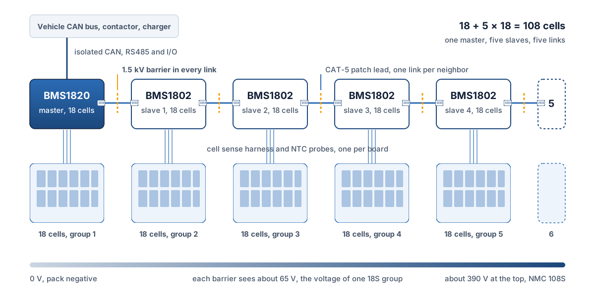
A slave minds its own cell group and nothing else. It is powered from those cells, wakes up when the master starts talking to it, and asleep it draws about 0.05 mW. Each slave needs two connections, the sense harness to its cells and the CAT-5 lead to its neighbor.
When the BCU2002 Takes Over
Above 882 V, and in any string where the controller belongs on the low-voltage side of the enclosure, the BCU2002 takes the master role with no cells of its own. It senses pack voltage up to 1500 V through optional isolated high-voltage inputs, reads two hall-effect current sensor channels, and collects up to 16 slaves over two 1.5 kV isolated RJ45 ports [4]. A 12 V to 80 V supply lets it sit next to the inverter and the site controller, its two CAN ports give each of them a bus of their own, and several BCU2002 strings run as one system in multi-master mode when the installation outgrows one string.
Step 3: Balancing Current from Capacity
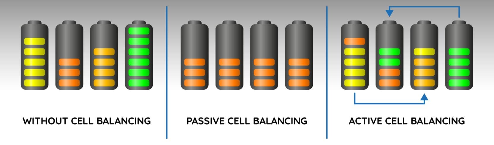
Balancing current is the number most often copied off a datasheet without anyone doing the sum behind it. The sum is short. Decide how much charge the weakest cells have to shed in one balancing window, the part of each charge during which the cells sit high enough for balancing to run, then divide by the balancing current. For a healthy pack we plan on about 1 percent of cell capacity per window. For cells of mixed age, or a wide temperature spread across the modules, the figure drifts toward 5 percent [7].
| Cell capacity | Charge to shed at 1 % | 420 mA, masters and BMS1202 | 800 mA, BMS3610 | 1000 mA, BMS1802 |
|---|---|---|---|---|
| 20 Ah | 0.2 Ah | 0.5 h | 0.25 h | 0.2 h |
| 50 Ah | 0.5 Ah | 1.2 h | 0.6 h | 0.5 h |
| 100 Ah | 1 Ah | 2.4 h | 1.25 h | 1 h |
| 280 Ah | 2.8 Ah | 6.7 h | 3.5 h | 2.8 h |
| 280 Ah at 5 % | 14 Ah | 33 h | 17.5 h | 14 h |
The row to sit with is the last one. A 280 Ah LFP cell that has drifted 5 percent needs more than a day of balancing even at 1000 mA, and no single charge will give it that. Packs of that size get balanced over several cycles, and then the schedule matters more than the current. The heat side of the same sum is in our passive balancing note.
It also helps to know what the balancing corrects. Cells in series all pass the same current, so a capacity difference between them does not grow from cycle to cycle. It only shows up as a smaller usable capacity, and balancing cannot change that. What grows is the state-of-charge gap from unequal self-discharge, 1 to 5 percent a month at room temperature and roughly doubling with every 10 degrees Celsius, so the warm end of the pack always drifts fastest [9]. A pack with 15 degrees between its coolest and warmest module needs a bigger balancing budget than the same pack with even cooling, and no balancing current fixes the cooling.
Step 4: Heat and the Balancing Window
Passive balancing turns the charge it sheds into heat in a resistor on the board. At 1000 mA and 4.2 V each channel dissipates about 4 W, so 18 channels running together on one slave would dump about 75 W into the enclosure. Every board handles that through two limits, both worth setting on purpose. The first is how many channels may balance at once, the maximum balancing cell count in LiMon, and turning it down trades balancing time for board temperature. The second is the window. Balancing starts once a cell passes a voltage you set and sits a set delta above the lowest cell, and it stops at a point you choose, so a pack that lives between 30 and 70 percent state of charge can open its window much earlier than one filled every night [3]. For the pack that is filled every night, a start voltage near the end of the charge and a delta of around 10 mV is a sensible place to begin.
Step 5: Isolation Above 60 V
Anything above 60 V DC is voltage class B in the vehicle standards, and class B means isolation between the live parts and anything a person or a low-voltage circuit can touch [10]. In a distributed BMS the live parts are the slaves. Module 1 sits near pack negative, module 14 several hundred volts above it, and whatever connects the two has to stand off that difference. A daisy chain is kinder here than a shared bus, because each link spans only the potential between two neighboring modules, around 65 V for an 18S group, and the full stack voltage never appears across a single barrier [11][12].
On our boards that barrier sits in the RJ45 ports at each end of the slave, rated at 1.5 kV for the BMS1802, the slave floats on its own cell group with no shared ground, and the lead between neighbors is a standard CAT-5 patch cable [5]. On the BMS1820, BMS3610 and BCU2002 the CAN Bus, RS485 and I/O lines are galvanically isolated as well, so the pack and the vehicle or building wiring never share a reference [3][4]. A slave that stops answering usually means a loose connector or a damaged lead, and we advise treating it as a pack fault that opens the contactor, because a pack whose cells cannot all be seen should not be delivering current.
Step 6: Cable Length and the Bus to the Outside
Inside the pack the modules sit side by side, so the chain links are short whether you plan them or not. The real cable question is the master's connection to the rest of the system, and on CAN Bus that comes down to bit rate [13][14].
| CAN bit rate | Practical bus length |
|---|---|
| 1000 kbps | about 20 m to 40 m |
| 500 kbps | about 100 m |
| 250 kbps | about 250 m |
| 125 kbps | about 500 m |
Our masters run CAN 2.0b at 125, 250, 500 or 1000 kbps, the BMS1820, BMS3610 and BCU2002 carry selectable 120 ohm termination on the board, and all of them speak Modbus RTU over RS485 at 115200 baud. A vehicle controller a meter away is happy at 500 or 1000 kbps. A storage rack reporting to a controller down the hall runs at 125 kbps or uses the RS485 port, which reaches several hundred meters at that baud rate. Our protocol note compares the two for each kind of host.
Three Worked Examples
| Example A | Example B | Example C | |
|---|---|---|---|
| Application | AGV or 48 V telecom pack | Light commercial vehicle, 400 V class | Utility storage string, 800 V class |
| Chemistry and capacity | LFP, 100 Ah, 16S | NMC, 50 Ah, 108S | LFP, 280 Ah, 250S |
| Master | BMS1601 standalone, or BMS1810 | BMS1820, 18 cells on the master | BCU2002, no cells on the master |
| Slaves | None | 5 BMS1802, 18 cells each | 14 BMS1802, 13 at 18 cells and 1 at 16 |
| Cells covered | 16 of 16 | 18 + 90 = 108 | 250 |
| Balancing per window at 1 % | 1 Ah at 420 mA, 2.4 h | 0.5 Ah at 1000 mA, 0.5 h on slaves, 1.2 h on the master's cells | 2.8 Ah at 1000 mA, 2.8 h |
| Isolation | None needed below 60 V | 1.5 kV chain, 5 links | 1.5 kV chain, 14 links |
| Bus to the host | CAN at 500 kbps to the vehicle controller | CAN at 500 kbps to the VCU | RS485 Modbus RTU to the site controller, CAN to the inverter |
| Notes | The integrated 250 A path on the BMS1601 removes the contactor | Same master firmware as a 48 V pack. The LCV note covers the vehicle side | 250 cells of LFP reach 912 V at full charge, past the 882 V of the 18S and 36S masters and inside the BCU2002's 1500 V |
Example B is the diagram from step 2. The master's own 18 cells save a sixth slave and a link in the chain, but they balance at 420 mA while the slaves run 1000 mA, so the master's group is always the last to come into line. On a pack with short windows, give the master the best-cooled group or size the window for the slower rate. Example C is the opposite case. At 800 V we would not want the master holding any cells, because a board that measures cells sits at cell potential, while a master that only aggregates stays on the low-voltage side next to the inverter.
What Usually Goes Wrong
Most of the questions we get on distributed packs come down to one of three things.
- Temperature sensors get counted last. A reasonable rule of thumb is one NTC for every four to eight cells [8]. An 18S slave with five NTC inputs covers that, but only if the probes end up at the thermal extremes of the module and not where the harness happens to be short.
- The current comes from the brochure and the window stays at the default. A pack that never climbs above 70 percent never reaches a default window, however much current the board has. Read the charge profile first.
- The chain gets treated like a bus. Links are point to point, one module to the next. A lead routed past a module to save a connector puts the whole stack across one barrier.
Conclusion
The six steps do not all pull the same way. Steps 1 and 2 are arithmetic, and the arithmetic is quick. Steps 3 and 4 are where a pack succeeds or fails, and they depend on the one thing no datasheet carries, the charge profile the pack will actually see. Most projects run the steps in this order, voltage first and balancing last, which is how a pack ends up with a brochure current and a default window.
We would turn the last two around. Decide first how often the pack will see a full charge and how long it will sit there, because that window is fixed by the application and by nothing you can buy. Then pick the balancing current that clears 1 percent of capacity inside it, and let that choice decide between the 420 mA and the 1000 mA slave. Isolation and cabling cost almost nothing to get right on the first sketch and a great deal to add afterwards, so they belong on that sketch. If your pack sits between the rows of the tables above, send us the voltage, the chemistry, the capacity and the module layout, and we will come back with a master and slave configuration and the balancing settings to start from.
References
- [1]Solar-electric forum, 18S battery BMS availability discussion
- [2]Akkudoktor forum, Diskussion 18S Batterie
- [3]LiBat, BMS1820 18S Master product page (slave count, balancing configuration, isolated interfaces)
- [4]LiBat, BCU2002 High-Voltage Battery Control Unit product page (1500 V sensing, 16 slaves)
- [5]LiBat Wiki, BMS1802 introduction (daisy chain, isolation and balancing)
- [6]LiBat, BMS1202 12S Slave Module product page
- [7]Analog Devices, Simplicity Wins: A Deeper Look into Active Balancing on BMS, Part 1
- [8]Battery Design, Cell Balancing and Battery Management System overview
- [9]EV Reporter, Understanding Self-Discharge of a Lithium-Ion Battery
- [10]L&T Technology Services, High Voltage Safety in Electric and Hybrid Vehicles (voltage class B per ISO 6469-3)
- [11]EE Times Asia, Achieve Robust Data Communications within High-Voltage BMS
- [12]Texas Instruments, Wired vs. Wireless Battery Management Systems (SLYY197)
- [13]Schneider Electric, CAN bus length versus bit rate
- [14]ISO 11898 CAN physical layer summary on the LiBat Wiki