Connecting a battery to a load is a switching problem before it is anything else. On one side sits a source that can deliver thousands of amperes. On the other sits a capacitor bank that is empty. Between them is a mechanical contact that has to close without being destroyed by the current in the first millisecond, then open against an arc that has no natural reason to stop.
How much those two moments matter is easy to underestimate. A Kilovac LEV200 is rated for 50,000 closing operations when the DC link has been precharged to 90 percent of pack voltage, and for 50 at 80 percent [1]. A GIGAVAC GX200 publishes the same pair [2]. Each pair belongs to one part, and what separates the two numbers is how it was asked to work.
The short answer
A contactor survives a battery power path when it closes onto a link that is already nearly charged and opens as rarely as possible under load. Five decisions get a pack there, and each one is worked through in the sections below.
| Decision | What this note recommends |
|---|---|
| Precharge resistor | The largest value that still finishes inside the time budget, R ≤ t / 3C, chosen by its single pulse energy rating |
| Closing threshold | The smallest remaining voltage gap the system allows, because peak make current follows the gap. Check the closing transient on a scope |
| Precharge mode | Time and current, or a link voltage threshold. A pure timer cannot detect a shorted link |
| Coil suppression | A zener or TVS clamp. A plain freewheel diode adds about 31 ms to the release time on a 24 V coil |
| BMS diagnostics | Link voltage sense, a mirror contact, and a check after closing that the precharge output has opened |
Closing onto a discharged link
An uncharged capacitor behaves like a short circuit, so closing the main contactor onto a discharged DC link is electrically the same as shorting it [3]. What limits the surge is the loop. Its resistance sets one ceiling, a few tens of milliohms of busbar, contact and capacitor ESR, and its inductance sets a second, the lower of the two winning. On a large link with short busbars the peak runs into tens of kiloamperes [4]. Contact bounce turns that surge into several, each arc carrying the contact spot past the melting point of its alloy, and when the contacts settle some of that molten metal solidifies into a bridge across them.
The awkward part is that a welded contactor keeps working. It conducts, the pack charges, the machine runs, and the fault only surfaces when something asks the contactor to open, which is usually a protection event.
A precharge circuit charges the link through a resistor until the voltage across the main contactor is small enough to close against. Two questions follow. How large that resistor can be and still finish inside the time the machine allows, and how small the remaining gap has to be before the main contactor is let in. The first is arithmetic, the second decides how long the contactor lasts.
Sizing the precharge
The calculation is a first order RC circuit with four inputs, and only one of them belongs to the pack designer. Pack voltage VBAT comes from the battery, link capacitance C from the inverter and everything else on the bus, the time budget t from the machine, and only the resistor R is yours.
Capacitance is the one to watch, because it tracks inverter power rather than anything the pack designer controls [3]. A precharge sized at design freeze becomes wrong the first time an integrator adds a converter. The time budget has its own ceiling, since automotive practice holds that precharge must not exceed 400 milliseconds [3].
Five expressions cover the charging side [3][5].
τ = R C
Time constant of the charging curve, in seconds.
uC(t) = VBAT (1 − e−t/τ)
Link voltage at any instant after the precharge contactor closes.
R ≤ t3C
Largest resistor that still finishes inside the time budget. Anything smaller also fits, at a higher peak current.
IPEAK = VBATR
Current at the first instant, seen by both the resistor and the precharge switch.
E = ½ C VBAT2
Energy the resistor absorbs on every precharge, independent of its resistance.
The three in the third expression is the number of time constants that counts as charged. Three brings the link to 95.0 percent of pack voltage, four to 98.2 and five to 99.3, and automotive practice sizes on three then lets a threshold check finish the job. Anything smaller also fits the budget, so the largest resistor the schedule allows is the gentlest on the hardware. That 95 percent is what the arithmetic predicts. Whether the link reaches it is the rest of this article.
The last expression is the one that catches people out, because the resistor absorbs the same energy the capacitor ends up storing, whatever its value.
From four inputs to a resistor specification
Take two packs on the same 200 millisecond budget. A 400 volt traction pack with 500 microfarads of DC link, and a 48 volt AGV pack whose lower bus voltage means a much larger link for the same power, 4700 microfarads.
| Step | 400 V pack | 48 V pack |
|---|---|---|
| Largest resistor for the budget, t / 3C | 133 Ω | 14 Ω |
| Nearest E12 value below it | 120 Ω | 12 Ω |
| Time constant, RC | 60 ms | 56 ms |
| Time to 95 percent, 3τ | 180 ms | 169 ms |
| Peak current, V / R | 3.3 A | 4.0 A |
| Energy per precharge, ½CV² | 40 J | 5.4 J |
Six lines of arithmetic and both parts are specified. What each specification demands depends on which number you read, and either design gives three.
| Framing | 400 V design | 48 V design | What it sizes |
|---|---|---|---|
| Energy in one pulse | 40 J | 5.4 J | Single pulse joule rating |
| Power during the pulse | 40 J / 180 ms = 222 W | 5.4 J / 169 ms = 32 W | Short term overload rating |
| Average, one start every 90 s | 40 J / 90 s = 0.44 W | 5.4 J / 90 s = 0.06 W | Continuous rating |
Each clears a different line on the same datasheet, the two powers are five hundred times apart, and the joule rating decides the purchase. A pulse much shorter than the resistor's thermal time constant leaves no time for heat to escape, so temperature rise depends on absorbed energy and thermal mass alone [6]. Forty joules forces a far larger part than 0.44 watts would suggest.
Allowing a factor of two or three in hand, the 400 volt order goes out as a 120 ohm wirewound rated above 400 volts with a single pulse rating near 100 joules, and the 48 volt design asks for 12 ohms near 15 joules. Compare candidates at the duration the design runs, because a joule figure means nothing without the pulse length it was measured over.
Pack voltage never enters the expression that sets the resistor. The two differ by the ratio of their capacitances and nothing else. Voltage enters the peak current directly and the energy squared, which is why the lower voltage pack gets the easier resistor and the harder switch.
The threshold decides contactor life
During precharge the resistor is large and the circuit heavily damped, so nothing oscillates. The interesting behaviour appears when the main contactor closes and the resistor is bypassed. Whatever voltage the link still has to make up, call it ΔV, drives a series loop holding the same capacitance C, an inductance L from busbar and cable routing, and no resistance beyond the busbar.
Rcrit = 2 √L / C
Loop resistance below which the closing step is underdamped and rings instead of settling.
I ≈ ΔV √C / L
Peak current when the main contactor closes, set by the voltage still missing from the link.
Take five microhenries of loop inductance with the 500 microfarad link, a fair figure for short busbars and a metre of cable. Critical damping would call for 200 milliohms, a busbar loop nearer 20 milliohms sits an order of magnitude under that, and the square root of capacitance over inductance comes out at 10 siemens. That square root is also the inrush figure at the top of this article, because below the critical resistance the inductance sets the ceiling, and a larger link on shorter busbars raises it into the tens of kiloamperes.
Measured capacitive make curves for the GX200 at 350 volts confirm the shape. Closing at 80 percent leaves 70 volts and peaks near 655 amperes, closing at 90 percent leaves 35 volts and peaks near 360 [2]. Halving the gap nearly halves the current, as the expression says it should.
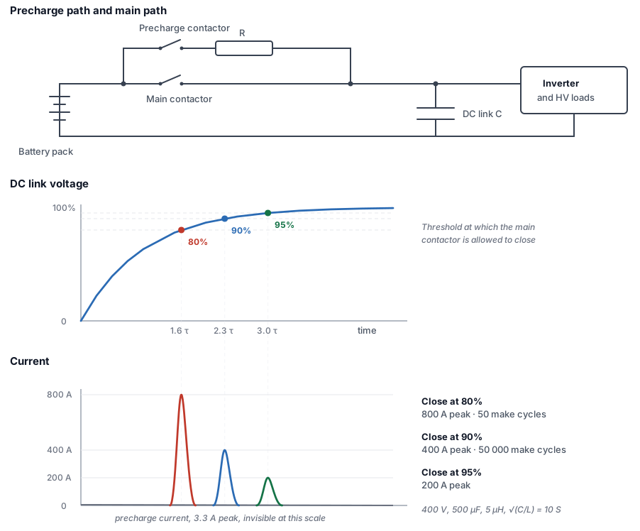
| Threshold at close | Residual ΔV on the 400 V pack | Peak make current | Precharge current at that instant |
|---|---|---|---|
| 80% | 80 V | 800 A | 0.67 A, 20% of peak |
| 90% | 40 V | 400 A | 0.33 A, 10% of peak |
| 95% | 20 V | 200 A | 0.17 A, 5% of peak |
| 99% | 4 V | 40 A | 0.03 A, 1% of peak |
That last column is the same instants seen on the resistor rather than the link, which is how a BMS holds a threshold without one.
Maximum make current for the GX200 is 650 amperes, and welding may occur at that level [2], so closing at 80 percent on a 400 volt pack crosses it on every start. That is the mechanism behind the two life ratings this article opened with. The threshold sets the current, the current erodes the contacts, and fifty thousand operations become fifty.
What the threshold does not set is the coefficient in front of it, because that square root belongs to one busbar and one link. The 48 volt design is no safer for being low voltage. Its larger link on shorter busbars gives a square root nearer 48 siemens, so closing at 90 percent still makes 233 amperes. One documented field case had a 650 volt pack charged to 617 volts, or 94.9 percent, where steady state current was 163.4 amperes and closing peaks still exceeded 3000 [7]. A percentage comfortable on one pack can be marginal on another, which is why the closing transient belongs on a scope.
Choosing the mode
| Mode | Closes when | Detects a shorted link | Requires |
|---|---|---|---|
| Time only | Timer expires | No | Nothing |
| Time and current | Current falls below threshold, minimum time passed | Yes | Current measurement |
| Voltage threshold | Link reaches a set percentage of pack voltage | Yes | Link voltage sense |
A pure timer encodes assumptions about a system the pack designer does not control. It assumes the capacitance is what the datasheet said, that no load woke up early, and that the capacitor is healthy. When any of those fails the timer expires anyway and hands the contactor whatever current the residual voltage produces. Either measured mode turns the sequence into a low energy health test before the main contactor commits.
Those two are closer to each other than the table makes them look. While precharge runs, the only current in the loop is the current through the resistor, and that current is the missing voltage divided by R [3].
uCVBAT = 1 − IIPEAK
Percentage charged, read from the precharge current alone.
A current threshold is therefore a percentage threshold, and the last column of the threshold table is that sequence expressed in amperes. What it costs is resolution, because the threshold is a few percent of a precharge peak that is itself a small fraction of the pack's rated current, and the sensor's full scale decides how high a percentage can be enforced in practice.
Across the LiBat master products any output can be assigned to precharge, in time only or time and current mode [8]. The second is the percentage threshold above, held on the precharge current. Reading the link itself is offered as an option rather than a standard function, and the BCU2002 can be supplied with one of its four isolated analog inputs measuring link voltage [9], which gives the third mode in the table. Those masters switch externally, so the pack designer supplies the contactors and the resistor. Below 250 amperes the BMS1601 takes the opposite route, carrying the switching MOSFETs, a 250 A shunt and both precharge paths on the board [10], which removes the external contactor and its welding failure mode but leaves the arithmetic where it was.
Opening is the harder half
Direct current never crosses zero [11]. An AC contactor only has to hold the arc apart until the next crossing, while a DC arc burns until something forces it out, which is why DC contactors carry a magnetic blowout to drag it off the tips into a chamber where it cools and collapses [11].
Many of these devices are therefore polarised. The field pushes the arc one way only, so current has to enter through the marked terminal, and wiring it backwards drives the arc towards the contacts [11]. The load life table shows what that costs. Against 50,000 closing operations at 90 percent precharge, the LEV200 allows twelve make and break operations at 200 amperes in reverse polarity, and one interruption at 2000 amperes before replacement [1]. A contactor should make at a near zero voltage difference and break under load as rarely as the system allows.
Those ratings are projected Weibull life at 95 percent reliability from extrapolated data, measured on resistive loads with at most 300 microhenries of circuit inductance [1]. A traction motor, a solenoid bank or a long cable run puts a real system outside the conditions they describe.
Release time is a design parameter
How fast the contacts separate decides how long the arc lasts, and that decides how much metal leaves the contact surface. The quantity that matters is release time, sometimes called dropout time, the interval from the coil command being removed to the contacts parting. It covers the decay of the coil current, the travel of the armature and the arc drawn between them. Only the first belongs to the coil drive circuit, and it is the one a design can lengthen by accident.
The numbers to design against sit on the contactor datasheet. On the Kilovac LEV200 they read as follows.
| LEV200 timing | Value |
|---|---|
| Close, including bounce | 40 ms typical |
| Bounce after close | around 7 ms |
| Release at 2000 A, arcing included | 12 ms maximum |
Closing is allowed to be slow, 40 milliseconds here and 15 on the faster EV200 [12]. Opening is not. Twelve milliseconds is the entire arcing window at full rating [1], and every millisecond the drive adds to the release is spent inside an arc the part was rated to hold for twelve.
The standard way to protect a coil driver is a freewheel diode across the coil. It works, and it does something else at the same time. The diode gives the collapsing field a low resistance path, so current keeps circulating and the armature stays held after the command.
Measured on a 24 volt coil drawing 290 milliamperes, the four common choices land a long way apart [13].
| Coil suppression | Added to the release time | What the driver sees |
|---|---|---|
| None | Reference, about 2 ms | Full back EMF spike, damages the driver |
| Diode | +31 ms | About a volt above supply |
| RC snubber | +8 to 18 ms | Set by the network values |
| Zener or TVS clamp | +3 to 5 ms | The breakdown voltage, 36 V here |
The spread comes from one quantity.
tdecay ≈ Lcoil IholdVclamp
How fast the coil current falls once the command is removed. The clamp voltage is the only term on the right that a designer chooses.
A diode holding the coil at about a volt drains it slowly, a clamp of a few tens of volts drains it tens of times faster, and that is what puts the rows of the table in order. It does not predict them, because the armature still has to travel once the current is below its holding value, which is why the fastest row lands at three to five milliseconds rather than under one. The delay grows with the coil too. The same diode adds seven or eight milliseconds on a small relay [14] and around thirty on the coil above [13].
A zener in series with a diode, or a bidirectional suppressor in one part, does the same job by the same mechanism, and a varistor is cheaper again at a clamping voltage the driver may not tolerate [14]. The transistor has to survive that clamp voltage at the peak coil current, and a suppressor with a standoff below the coil supply will conduct while the contactor is meant to be held.
The clamp is the answer, and it costs nothing close to a welded contactor. Two traps remain. Many integrated relay driver chips carry freewheel diodes across their outputs, so a design can acquire delayed opening without anybody choosing it [14]. And most HV contactors already suppress internally, the EV200 economizer holding back EMF to zero volts [12]. That describes what the contactor puts onto the supply wiring. Its coil current still decays at its own rate, already inside the datasheet release time, and what the figure does not license is a second, slower clamp outside.
What the BMS can and cannot see
A battery management system commands the contactors, so it is tempting to assume it knows their state. It knows what it commanded.
| Visible to the BMS | Not visible without extra hardware |
|---|---|
| Pack voltage and current | Link voltage beyond the main contactor |
| Whether current fell inside the expected window | Whether the precharge contactor actually opened |
| Whether the sequence timed out | Whether a main contact is welded while current is zero |
| Its own output command state | Whether the coil driver actually energised the coil |
Three additions close most of that gap. A voltage sense on the link side of the main contactor turns every diagnostic in the right hand column into a measurement, and it still reads once the precharge current has stopped. A mirror contact, mechanically prevented from indicating open while the main contacts are welded, gives the state of the contactor itself, and the EV200 variant carrying it meets IEC 60947-4-1 Annex F [12]. A check after closing confirms the precharge output opened and the resistor is out of circuit, which is the difference between a pulse rated part and a burnt one.
Before you ship
Measure the link voltage through a precharge and compare the time to threshold against the calculated time constant. Arriving early means the real capacitance is lower than claimed. Never arriving means something is drawing current, and a converter enabled too early is the classic phantom fault where the pack is healthy and the field replaces the BMS.
Measure the closing transient, which almost nobody does and which is the only place the residual voltage difference becomes visible. Then measure the release under load, from coil command to zero current, against the datasheet figure. That catches an undocumented suppression diode, a driver chip with an internal one, and a contactor beginning to stick.
Force a failure by precharging into a load and confirm the system latches instead of retrying, because a fixed retry interval turns a pulse rated resistor into a continuously dissipating one [5], and 40 joules every two seconds is 20 watts.
Confirm that a failed precharge raises an event somebody can find later. Precharge conditions sit in the protection set on the LiBat masters and are read from the event view in the LiMon PC Tool [15]. Record contact resistance at commissioning too, because the 30 percent rise marking end of life means nothing without a baseline [7].
References
- [1]TE Connectivity Kilovac LEV200 series contactor datasheet. Source of the capacitive make life ratings at 90 and 80 percent precharge, the reverse polarity and break ratings, the 300 microhenry qualification and the operate times.
- [2]Sensata GIGAVAC GX200 product comparison. Source of the measured 350 VDC capacitive make curves and the 650 A welding threshold.
- [3]Texas Instruments SDAA145A, DC-Link Capacitor Pre-Charge Designs in Automotive Systems. Source of the RC sizing equations, the link capacitance range and the 400 ms duration limit.
- [4]Charged EVs, a closer look at capacitor precharge and inrush current control. Source of the inrush magnitude figures.
- [5]Miba Power Electronics, precharge resistor calculation. Source of the resistor sizing relations and the average power expression for repeated cycling.
- [6]EPCI, resistors pulse load and derating design guide. Source of the adiabatic pulse behaviour.
- [7]Durakool, HVDC contactors and failure modes. Source of the 650 V field case and the contact resistance service threshold.
- [8]LiBat BMS1810, 18S master BMS with software configurable precharge in time only or time and current mode, assignable to any output.
- [9]LiBat BCU2002, multi-master battery control unit with four isolated analog inputs. Link voltage measurement on one of them is offered as an option and is not part of the standard configuration.
- [10]LiBat BMS1601, 16S standalone BMS with an integrated 250 A power path and onboard precharge and predischarge paths.
- [11]VIOX, why DC contactors need special arc extinction. Source of the zero crossing argument, the magnetic blowout mechanism and the polarity effect.
- [12]TE Connectivity Kilovac EV200 series contactor datasheet. Source of the coil economizer figures, the 15 ms close time and the IEC 60947-4-1 Annex F mirror contact reference.
- [13]VIOX, coil suppression techniques compared. Source of the dropout times measured on a 24 V 290 mA contactor coil for diode, RC snubber and zener suppression.
- [14]Durakool, a layman's guide to coil suppression. Source of the small relay release figures and the driver clamping trade-offs.
- [15]LiMon PC Tool, configuration and diagnostic software for LiBat battery management systems. Its event status view is where protection events, precharge conditions among them, are read from a master.